


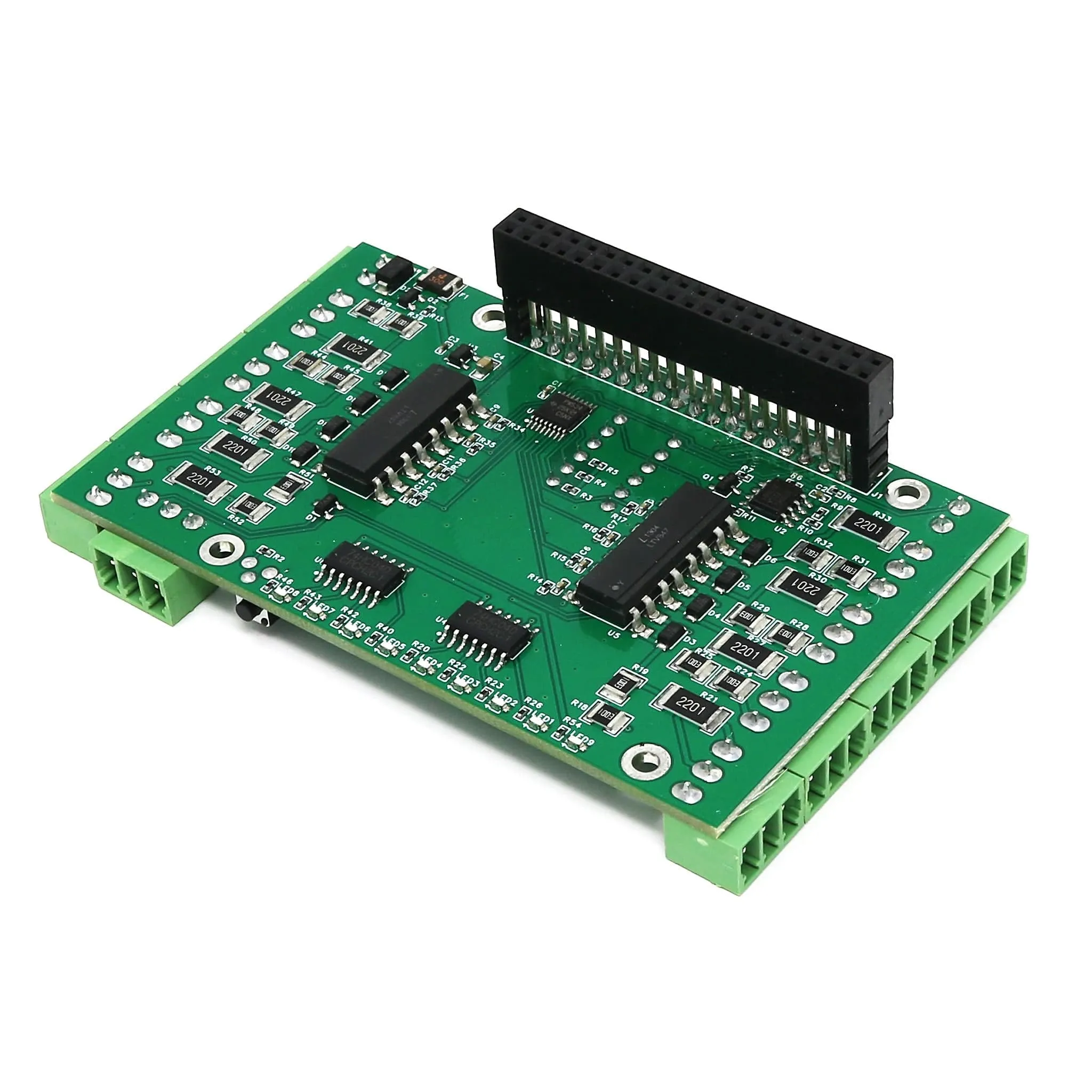
The can read 26 input signals through the GPIO header, but these pins are wired directly to the local processor. Additional hardware can be required to connect them to real-world things at real-world voltages!
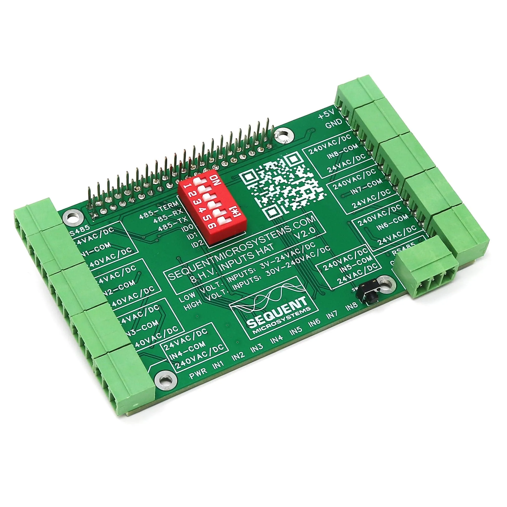
This card has eight optically isolated digital inputs, from 3V-24V or 48V-240V. Inputs can read both DC and AC signals. Separate input pins are provided for low or high-voltage ranges
The card communicates with Raspberry Pi using only the I2C port, leaving all the other 24 GPIO pins available for your use. It has also an RS-485 port, a power LED and a push-button that can be used to shut down the Raspberry Pi.
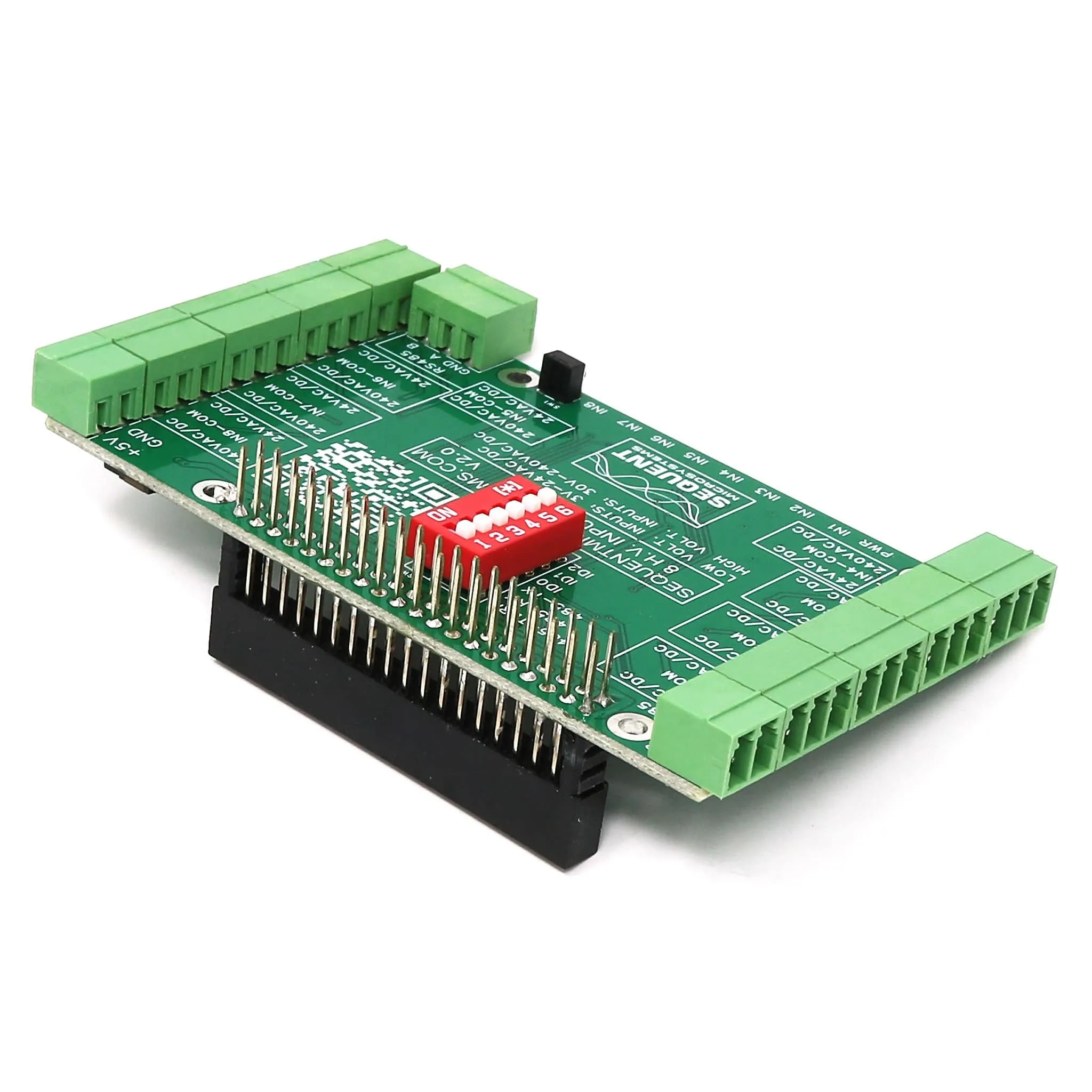
Pluggable connectors make the card easy to use when multiple cards are stacked up.
For any technical questions about this product please email
Features
- Eight HV (high-voltage) universal opto-isolated inputs 3V-24V or 48V-240V AC/DC
- Eight layer stackable to 64 inputs
- LED Indicators on each input
- Pluggable Connectors 26-16 AWG wires
- Separate low/high voltage connectors for each input
- Software self-test
- RS485 Transceiver
- module
Compatability
The card is compatible with all Raspberry Pi versions from Zero to 4. All stacked cards share the I2C bus using only two of the Raspberry Pi’s GPIO pins to manage all eight cards. This feature leaves the remaining 24 GPIOs available for the user.
Power Requirements
The card needs 5V to operate and can be powered from Raspberry Pi or from its own 2-pin pluggable connector. The card draws 10mA. If power is applied to the 2-pin pluggable connector, no other power supply is needed for the Raspberry Pi.
Stacking Multiple Cards
Up to eight cards can be stacked on your Raspberry Pi. Each card is identified by jumpers you install to indicate the level in the stack. Cards can be installed in any order. A three-position jumper selects the stack level.
For your convenience, two jumpers are provided with each card.
Reverse Power Supply Protection
The board is protected against accidental reverse power supply with a 5.8A, 39 mOhm MOSFET which breaks the ground line if reverse power is applied.
Reset Pushbutton
Shutting down the Raspberry Pi by turning off the power can result in SD Card failure. To prevent this, a shutdown command needs to be used before power cut-off. But this requires a monitor, keyboard and mouse connected to the Pi.
A momentary push-button installed at the edge of the board provides a convenient way to shut down the Raspberry Pi. The button is routed to pin 37 (GPIO 26). You need to write a script that monitors this pin, and if pressed for more than the desired time, issues the shut-down command.
DIN-Rail Mounting
The card can be installed parallel on a DIN-Rail using the , or perpendicular using the .
Software
Software Interfaces
You can write your own application using the or provided. No programming is required if you use the we supply. You can drag-and-drop the functional blocks to design your application. Examples are provided at GitHub.
RS485 Port
A standard RS485 transceiver permits the Raspberry Pi to communicate using any protocol including MODBUS, PROFIBUS, camera PTZ control, etc.
The transceiver is connected to the serial port of the Raspberry Pi from the GPIO connector, pins 8 (GPIO14, TxD0) and 10 (GPIO15, RxD0). The Rx line is routed through a 2 pin jumper. The jumper needs to be installed in order to use the RS485 port. If the jumper is not installed, both pins can be used as GPIO's. An on-board 120 Ohms terminator can be applied through the jumper located next to the port.
Drivers & Libraries
- module
Electrical Specifications
- Power Supply: 5V/8A pluggable connector with reverse polarity protection
- Onboard resettable fuse: 3A
- Opto-isolated Digital Inputs:
- Input Forward Current: Typical 5 mA, maximum 50 mA
- Low Voltage Input Series Resistor: 2.2K
- High Voltage Input Series Resistor: 120K
- Isolation Resistance: Minimum 1012 Ω
Mechanical Specifications
Package Contents
- 1x 8 Inputs card
- 2x Jumpers
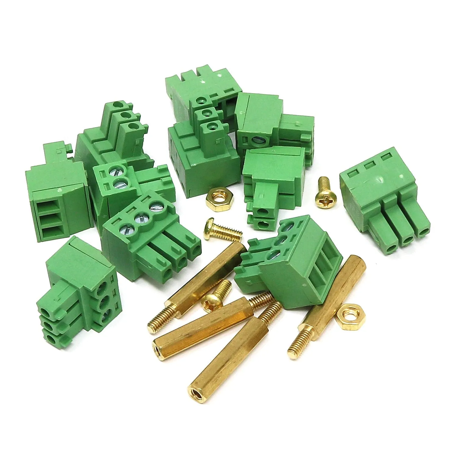
- 10x Mating plugs (8x 3-pin, 2x 2-pin)
- Brass Mounting Hardware
- 4x M2.5x18mm male-female standoffs
- 4x M2.5x5mm screws
- 4x Nuts
Revision History
- As of 30/01/2024 we are now stocking V2.0 - an updated version with a DIP switch and more pluggable connectors


